Timing
Photographer Ansel Adams said “Sometimes I arrive just when God’s ready to have someone click the shutter”. I like that quote even though I must admit it doesn’t much apply to the subject of this report. Regardless, it’s a good “writer’s trick” to include a wise quote at the beginning of an otherwise dry piece in order to improve its readability. I think I will do this more often…
Timing Your Off-Field Landing
When it comes to flying any aircraft – particularly 2-stroke engine powered Ultralights – you can improve the odds that you will not experience an in-flight engine failure by altering the MTBF Continuum. MTBF ( Mean Time Between Failure) – is the concept that there is a predictable or estimable point in time when a machine or system (or any other object for that matter) will fail during use. A hammer has an MTBF as does a computer hard drive. I have experienced the failure of 2 hammers in my life but seen many more hard drives “go South”. The soon arrival of the point of failure for a hammer is usually evident by visual inspection. Hard drives, on the other hand, give you little or no warning before they give up the ghost. In addition, they often provide the additional “negative bonus” of taking countless hours of your hard work to “hard drive heaven”. My experience in using them for the last 25+ years is that their advertised MTBF figures are pure fantasy – absolute meaningless speculation.
I say all this because I had to make a decision at the end of the 2012 Flying Season. My Rotax 503 Engine had faithfully rotated the air screw of my MXL over the last 4 years providing me with 327 hours of flight. Without a doubt it has been the finest engine I have ever had the good fortune to own. Back in the 1980’s, when I flew my first Quicksilver (an MX), engine failures were a constant and real occurrence. Over a few years of flying with the old Cuyuna engines, I had the opportunity to land without power no less than 6 times.
My flying instructors taught me well before receiving my Private License as a 17 year old. They would jerk the throttle at seemingly random moments and say “OK. Where are you going to land?“. After lowering the nose to get airspeed stabilized I would look around, point and say “Over there”. If the spot met with the instructor’s approval he would say “OK. Give it some power” and we would level off and move on to other tasks. I went through the exercise so many times that I was really surprised one day when the instructor didn’t call for me to power the Continental back up. So, I just followed through and made a dead stick landing on a mowed grass farm field. He said, “Good job. Now you get to make a soft field takeoff“. We jumped back into the air. Even though that was good training, it is pretty rare in the Certificated Aircraft World that an engine-out landing is required. Most guys figure they can do it if they have to, but never really have to prove it. When flying an Ultralight, though, the possibility of needing to demonstrate one’s proficiency at making an “unscheduled” dead stick landing is not “academic” – at least in the early days. Much about that has changed in the intervening 30 years. I bought my current Rotax 4 years ago from Air-Tech of Louisiana. It has run flawlessly during that time. I can’t tell you how nice that is… (I have to constantly warn myself not to get complacent, though)
What Is The Rotax 503 MTBF?
Which brings me to the point of this writing exercise. Rotax tells everyone to replace a 503 crankshaft at 300 hours of use. Some very reputable guys will tell you this is a Lawyer’s Ploy so as to exempt Rotax from any blame for crank failure should a particular owner be less than careful with his engine power settings or fuel/oil mixtures. They will tell you the cranks are good up to 1,000 hours. I tucked that data into the “deep consideration” memory partition of my cranial computer.
There is also the idea out there that you can run the pistons and rings “somewhat indefinitely” as long as the measured cylinder compression is in tolerance. I filed that info in the appropriate place also.
The third major area of wear consideration in these rather simple engines is the bearings and seals. This is where the great seers of the Rotax World become less confident in their prognostications. The PTO (Power Take Off) seal is visible on the exterior of the motor and can be examined for dryness, cracking or distension. Not so for examination of the inner crank bearings or the front seal. Some will say the condition of the bearings can be detected by feeling the crankshaft as it is gently turned. I believe this “bumpiness” or “sliding” can be reliably detected in the mechanic population at the same percentage as the rarest of safe crackers using “finger feel” to detect the movement of tumblers within the lock of a wall safe. This talent is extremely rare and I suspect tales of success using this method have a tendency for exaggeration. It comes off to me like “dowsing” for water wells.
Upon evaluation of all this evidence, my solution was to “blow it all out“. I decided to have the engine completely overhauled with a new crankshaft, pistons, rings, seals and bearings. In addition, I replaced all three of the propeller reduction drive bearings AND all the fuel lines. In other words, I decided to replace all wear items on the plane – tires & inner tubes, too.
Don’t Wait For The Failure – Continually Move It Out To Infinity (and Beyond…)
Over my years of flying Ultralights I have listened with wonderment to guys who talk about “making ’em last” (there is some of this thinking with certificated airplanes, too, and definitely automobiles). What I mean by that is they will look at an old drive belt or an old spark plug or an old nylock nut or some old fuel line or a worn electrical wire and actually be proud to leave it on their plane rather than changing it out with a new part. They seem to actually believe they can “read” the MTTF (Mean Time To Failure) of various objects. At the root of it, I think they think they are saving money. I don’t get that. There is absolutely NO SAVINGS in running stuff ’till it breaks. This follows with cars, bikes, motorcycles, hoses on washing machines – you name it. Invariably when you play that game, the part will fail at a time which will cost you way more in time, money and hassle factor than it ever would cost when you replace it on your terms.
Here’s a good method: Envision old wear parts as broken parts. When you do this you give yourself the power to take that “failed part” and throw it in the garbage. That is how you can best eliminate the possibility you ever learn what I’ll call the ATTF – Actual Time To Failure – of your motor or other system.
Of course we live in a fallen world and failure can still occur when everything has been done to prevent it. The odds go with prudence, though, every time.
Part Of Prudence Is Picking A Prime Partsmith
In an earlier posting (HERE), I described the brain wrangling I put myself through to arrive at the conclusion that The Sky Surfer was not up to the skill level I expect as the person to rebuild my Rotax 503. There is no reason to go over that again. I had Rotax Rick of Naples, Florida to re-build my engine.
Rick did his job. Now I’ll get to some pictures and descriptions of my part of this major overhaul.
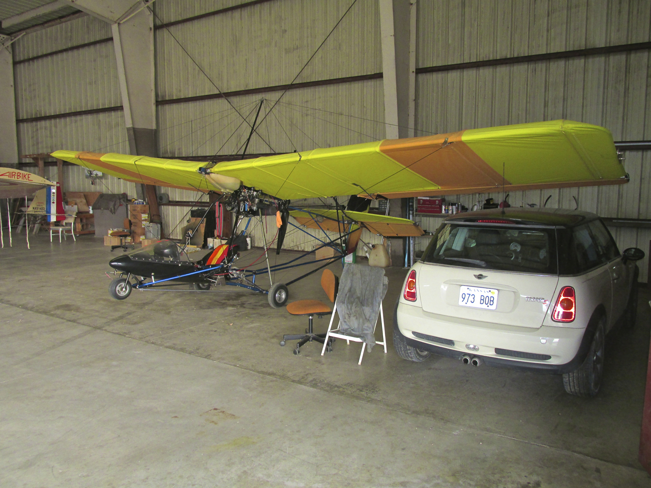
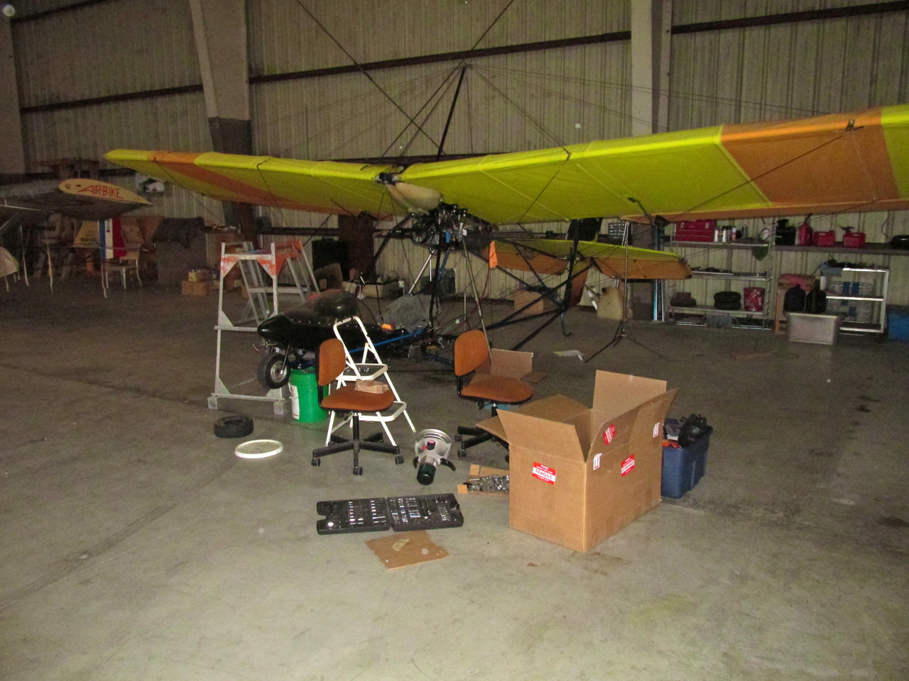
Friday, 30 Nov 2012 – Quicksilver At Rest Minding Its Own Business
Prep Work
I came out on Friday afternoon to check things over and remove spark plugs and fuel lines and things like that in preparation for the engine drop the following day.
Before starting, I took loads of pictures of the engine and drive train as “templates” to increase my chances of re-assembling the different sections the same way.
Did I Really Believe That?
I arrived early in the morning Saturday 1 December to take the engine off. I had it in my mind I would do this in a couple of hours, pack it up, take it to FedEx to ship it to Rotax Rick and be back in my office with time to get some “business” work done that the afternoon. Get Real. I wasn’t even close. Definitely “wishful thinking”. I was in the hangar until darkness started to fall.
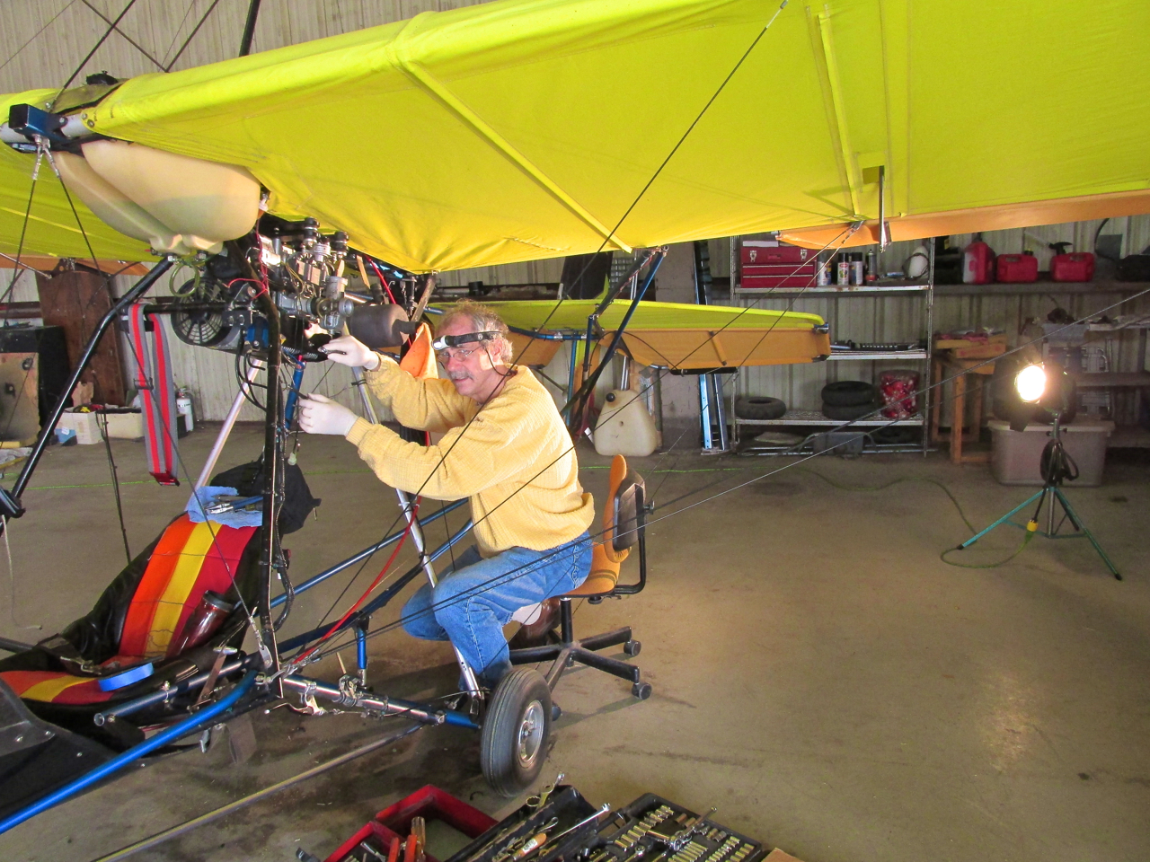
Brian The Ultralight Surgeon – Photo by Joe Bryant
Let There Be Light
Above you can see that I like to use a lot of light. The spotlight in the background is one I use for shooting TV spots and other moving pictures. It has a 1,000 watt tungsten bulb and is very bright. It has the additional benefit in a chilly hangar of putting out substantial heat. Sometimes I use 2 or 3 of them. Of late, I have also taken to wearing the headlamp you see. If you haven’t used one of these LED headlamps when working you should try it. They help a lot.
My buddy Joe Bryant showed up at the hangar around 10:30 am. I asked him to take the picture. It looks like I had not accomplished much in 2+ hours. At least it is not obvious what I had accomplished in a couple of hours. My method is slow but meticulous. Every bolt, nut and washer I removed was tagged and described using that special blue tape you see sitting on the pilot seat. I am glad I did this because I had no problem putting the right bolt in the right hole 3 weeks later.
Brian and Joe Prepare for The Big Lift

The MXL Is Officially A Glider
Calypso Isometrics
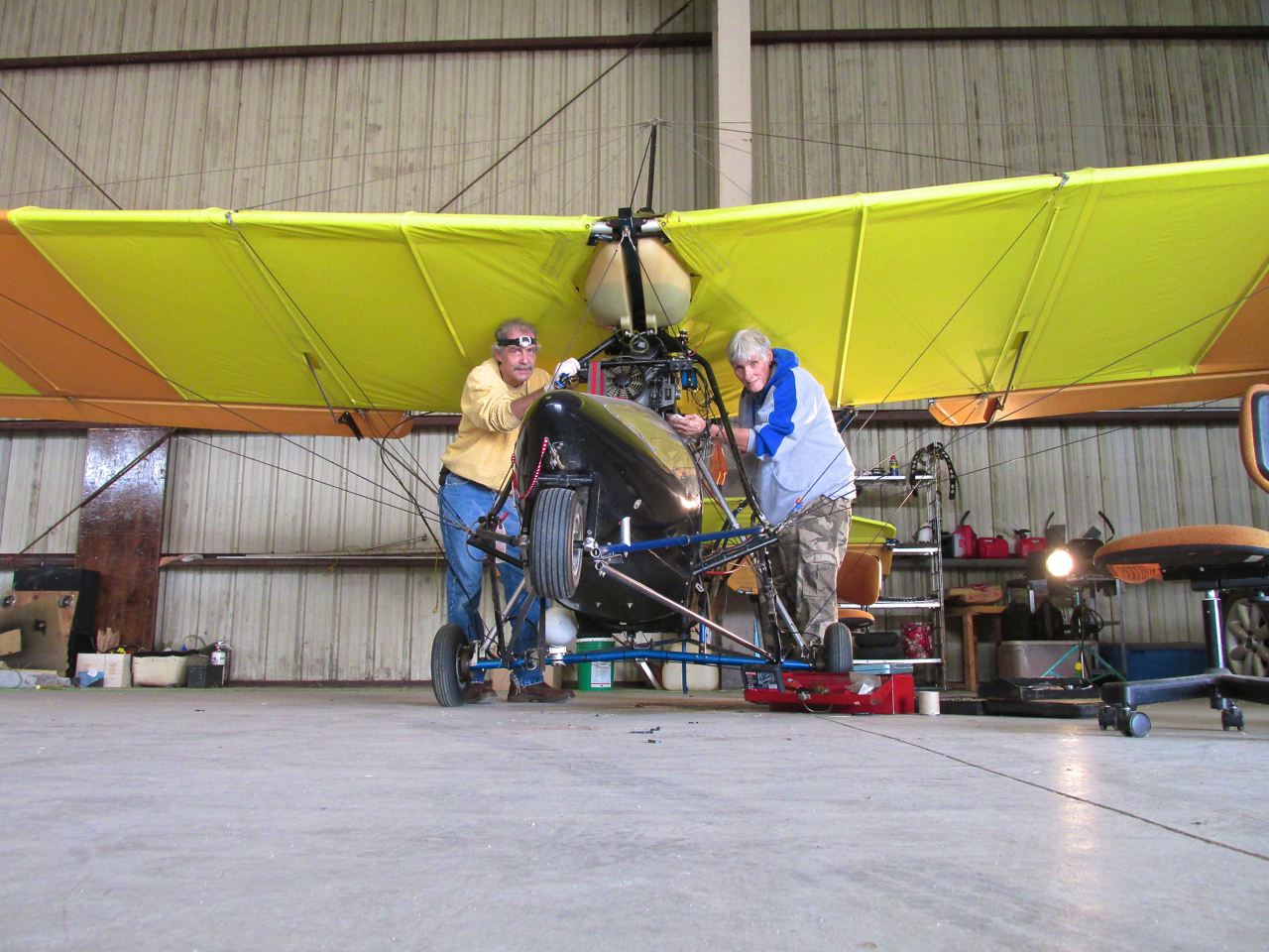
Since my buddy Joe was hanging out with me, I enlisted him in the critical phase of lifting the motor out from under the wing. It only weighs about 70 pounds but it is suspended in a myriad of aluminum tubes. Because I am 6′ 1″ tall and the underside of the wing is about 4.5′ off the ground, I had to reach in to lift the motor out from a “hunched over” stance. It is not a completely horrible job but for about 20-30 seconds it can be rather intense. Once the engine is released from the root tube mount, you have 70 pounds of dead weight to ease out of the maze. Dropping it on the floor is not an option.
Brian’s Big Contribution To Aircraft Maintenance
I have made one contribution to the art of Quicksilver engine removal and replacement. At least for those that feature an “under wing” engine placement like the MXL (some models have the engine on top of the wing).
The first few times I removed an engine, the guys who coached and/or assisted me would just let the thing hang from the engine mount bolts and then hold the engine while unscrewing the nuts. That method turns seconds into hours as you hold the motor in place while your buddy tries to get all 4 nuts off the mount bolts in quick order (I actually did it that way by myself once!). Almost always, a bolt would start spinning and not release its nut OR suddenly a nut just flies off without warning OR the last nut would not come off at all. In the event of the last listed bad turn of events, you would need to quickly re-apply at least one nut diagonally so you could rest and try again. It was a real hassle. One day I decided to analyze the situation to find a better way. The solution came in the low-tech guise of The Tie-Wrap. These amazingly cheap but strong plastic things are employed all over the Quicksilver to guide wires and cables along the tubing. I decided they would be strong enough to temporarily hold the engine up while I removed ALL the engine mount nuts and bolts. Then all I had to do was slide the bottom engine mount out of its Tie-Wrap “loops” and the engine was free. This method has helped enormously ever since and it worked well Saturday. You’ll see a closeup photo of the tie-wrap application during the re-mount phase of this report.

Like Two Hunters With A Trophy
Of course we were very pleased with ourselves after accomplishing this feat and documented the moment of triumph above. It was 4 pm in the afternoon when I finally got the motor into the trunk of the Mini. By then I was too tired to mess with packing it up. All I could do after that was go home and take a nap…
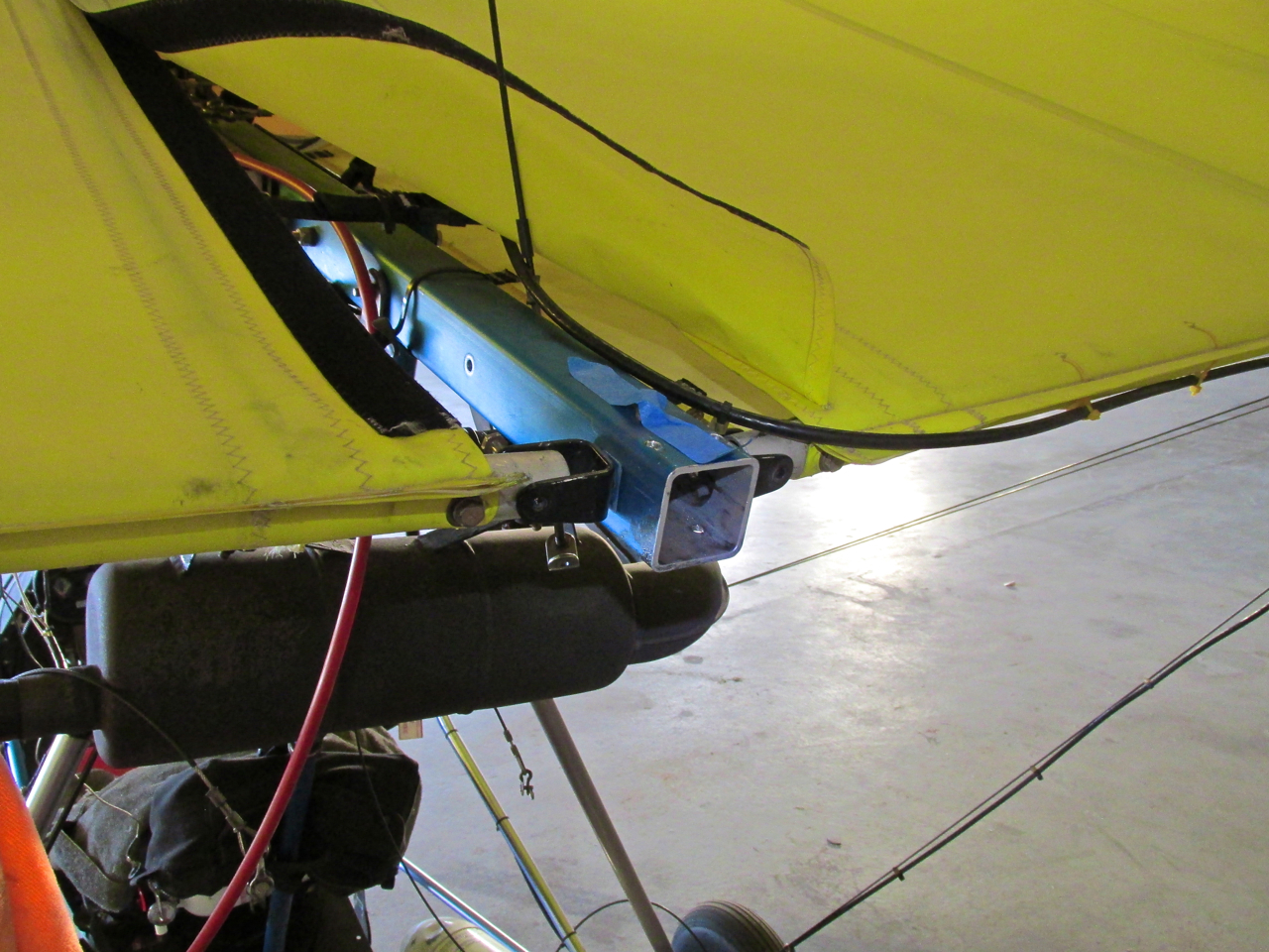
The Drive Section With The Belts Removed
The drive section was left for another day.
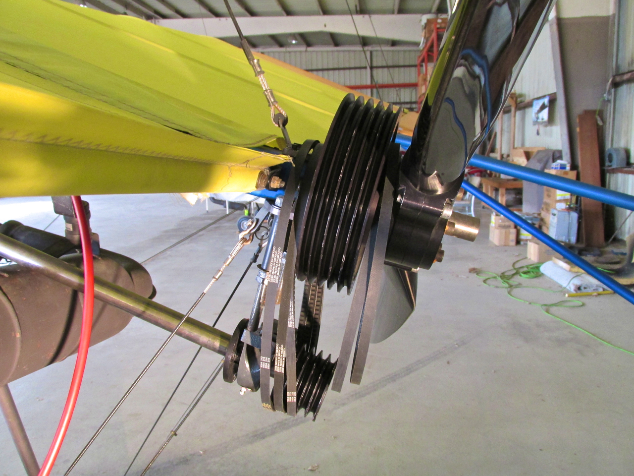
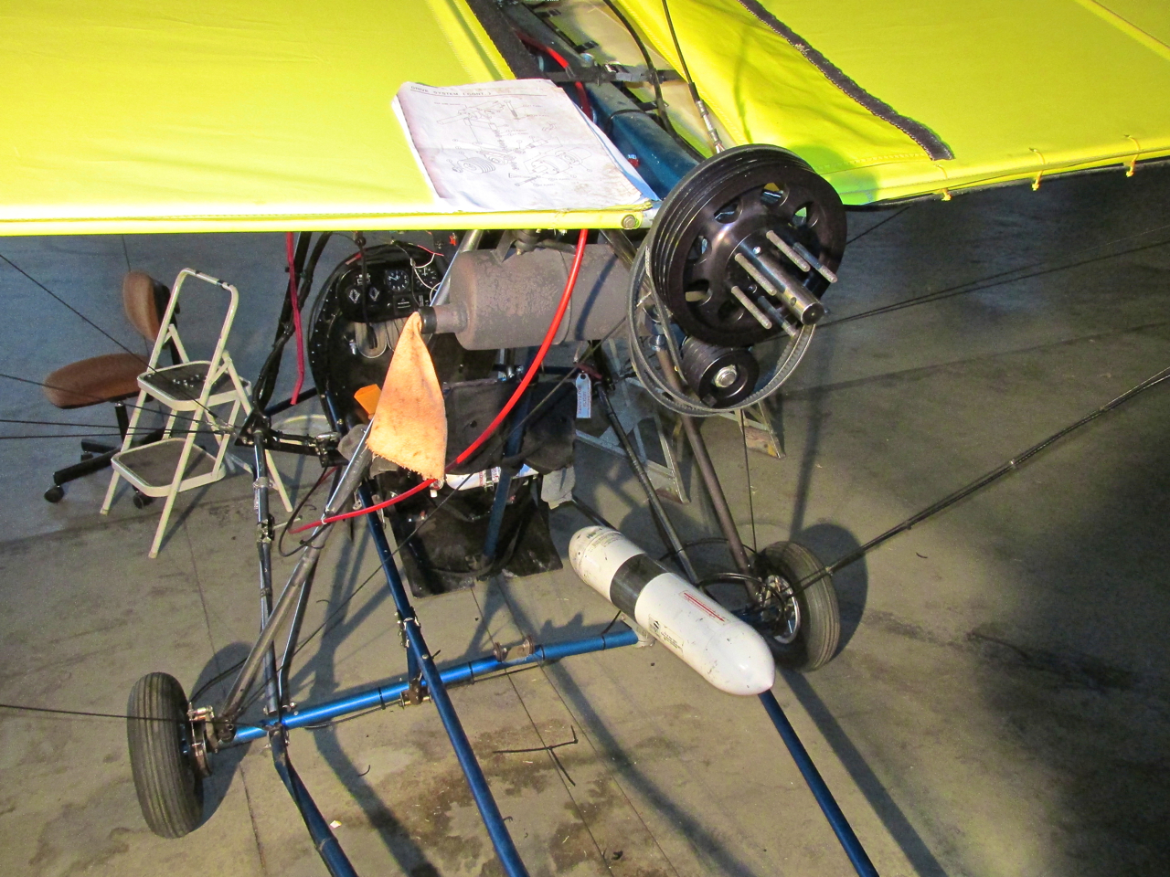
Props, Pulleys, Belts and Bearings Removed
Looks Can Be Deceiving
I figured after getting the motor off, removing the Prop drive Assembly would be a breeze. Wrong. It took me TWO (half) days to get the Prop Drive stuff off. The prop shaft goes into that box tube you see above (called the Root Tube). It has a bearing at the front end where you see the empty bolt hole on the side of the root tube. The trailing edge wing spar bolts must come out before the bearing carrier can be removed. It was not easy to do. If I had been smart enough to lower the king post, which would have relieved the tension of the taut flying wires – it would have been MUCH easier. I won’t forget that next time…

Tagged And Stored For Later
Aircraft Dis-assembly Marker Blue Tape
Above you see the work table I used to array the parts I took off the plane. Also you can better see the special blue tape I used to mark all the items as I took them off the machine. If you look closely you can see descriptions on them. This method takes a little more time during dis-assembly but sped up reassembly enormously. Here’s a trade secret for you. This tape doesn’t come from a Federally Approved Airparts Store. The blue color is just happenstance. Before heading to the airport the day of the dis-assembly, I looked around my garage for some duct tape for tagging. I am SO GLAD I didn’t find the duct tape, but instead, found this blue masking tape. Masking tape removes easily without leaving glue behind (like duct tape does). It worked perfectly for the job. Duct tape would have been a mess.

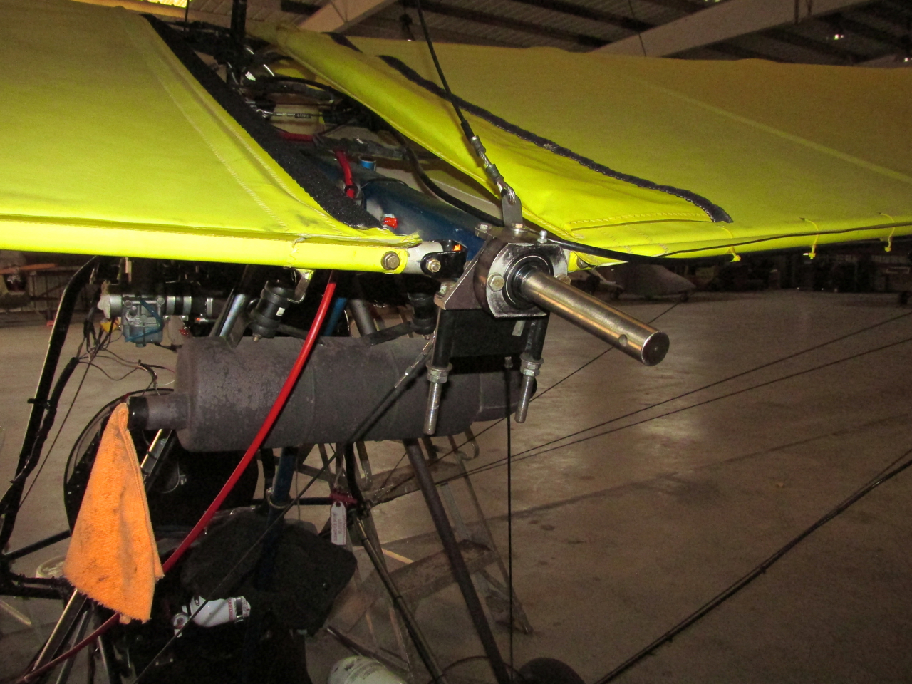
The Drive Assembly (Sans Pulleys)
Drive Assembly Gets Attention, Too
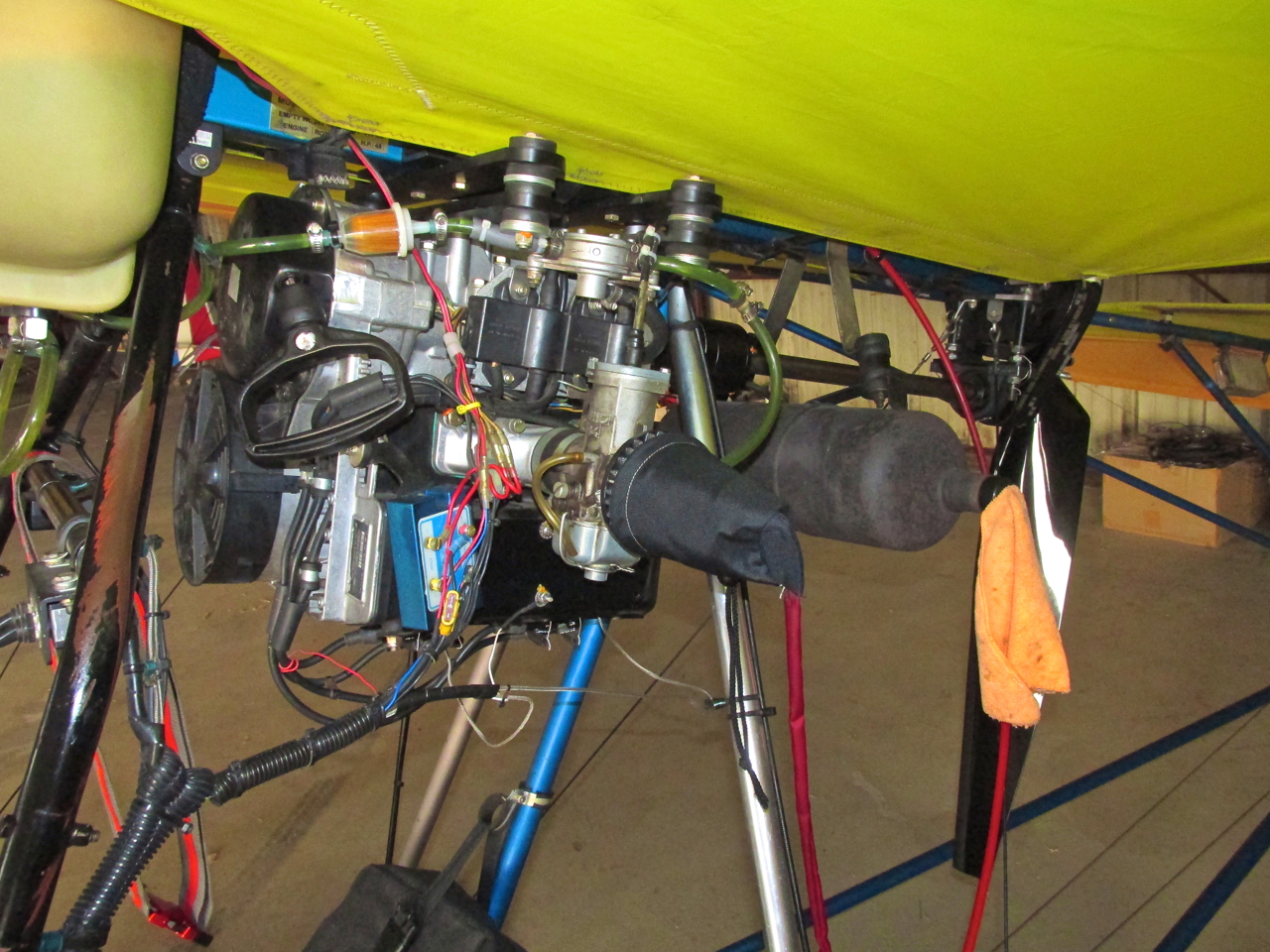
After spending an inordinate amount of time removing the drive suite, I took the picture of it above. To the lower left you see a pillow block bearing. This bearing needs to handle rotational speeds up to 6300 RPM. While that is not an outrageous speed for a bearing to handle in the world of engineering, I am told that the shaft, which attaches directly to the PTO of the Rotax, flexes “quite a bit” as the motor goes through different power settings. The Black Cylinder at the top of this shaft is a vibration-dampener to soften up the 2 Stroke Pulses.
Inside the cylinder at the middle of the picture is the front prop shaft bearing that goes on the tapered end of the rod to the right, which is the propeller shaft. The business attached to the prop shaft contains another bearing. In keeping with my desire to push the system’s MTTF off to infinity, I replaced all three bearings.

Santa Brought Me A Late Present
Merry Christmas!
Above is the box left on my porch containing the overhauled Rotax Engine after being shipped to me by Rotax Rick of Naples, Florida. Even though the porch decoration represents Christmas, the picture above was taken on 4 January 2013. Regardless, it was my Christmas present for this year (and a few more Christmases into the future…). Rick did a great job on this overhaul and I recommend him highly to you. He is an A&P Mechanic and has done hundreds of rebuilds. I know he works on the Rotax line of engines so you can count on him for that. He may work on other brands of motors, too, but I cannot say. Here is his address and phone number if you want him to quote you a deal:
Ron Davis
940 Ninth Street S.W.
Naples, Fla. 34117
(239) 572-0021
He gets it done faster than you expect and is very reasonable on price.
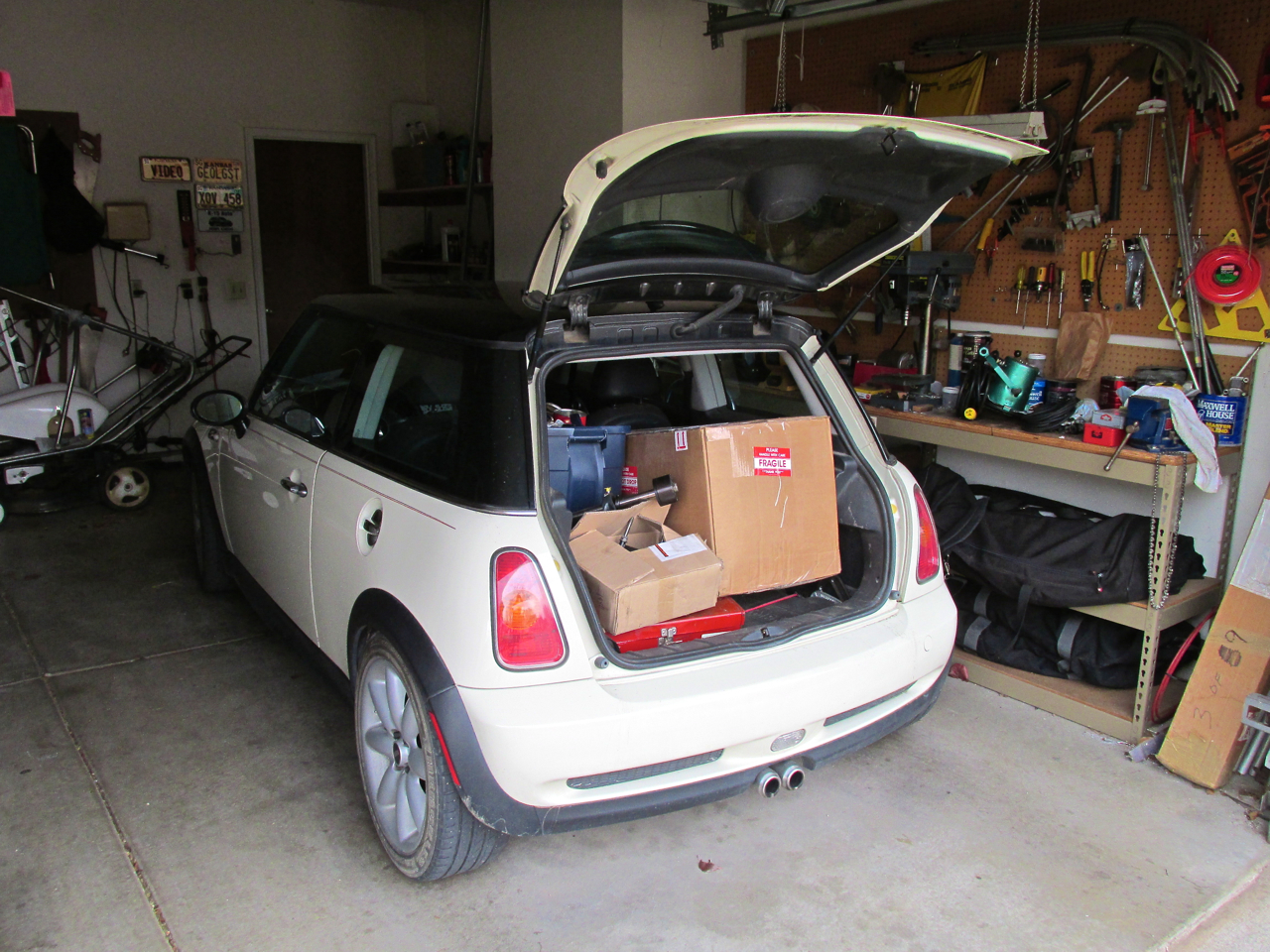
Packed And Ready To Roll
The Mini Cooper S Production Vehicle
Above you see my Cooper S Production Vehicle. I call it that because it can hold the Camera, Tripod, Lighting, Green Screen and Grip Tools I need to shoot pretty much any TV commercial or interview. The only time I need a bigger vehicle is when I use my 12′ Crane or 10′ Slider Dolly. Other than that the Mini performs like a Maxi. (I should point out that I removed the rear seat and replaced it with an after-market platform) It has plenty of room. In the picture above I had loaded every part and tool I might possibly need at the hangar in addition to 3 work lights. Selby Aerodrome is 20 minutes from my home. I avoid wasting time driving back and forth. This day, I had planned well and put in a whole day re-installing the engine without having to come back for anything. The only downer was that it was 31 degrees in the hangar. But, I kept moving and did not feel the cold much.
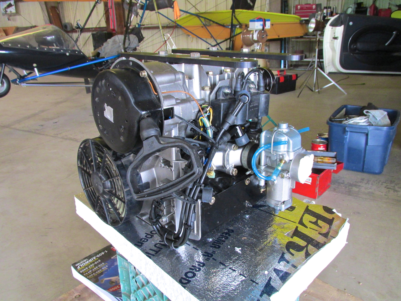
Shiny – Like New

Top Side – Showing Engine Mounts
As Good As New
Again, Buddy Joe Bryant showed up to help me with the critical lift portion of the re-install. I took the two pictures above so you can see how nice the Rotax looked after coming out of the box. Rotax Rick painted it up nicely. The shipping crate was solid, too. The first order of events was to re-attach the motor mounts. They are obvious in the shot directly above. The mounts mate to two others of similar dimension attached to the MXL Root Tube. Bringing them together is when the previously described Tie Wrap Solution pays off.
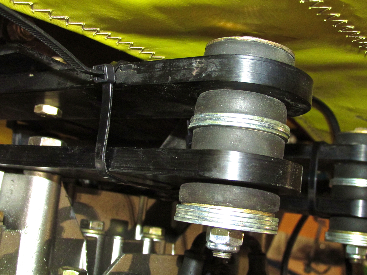
A Close Up Of “The Tie Wrap Solution”
Once the nuts are tightened under the fender washers you see above, the tie wraps are cut. One of these days I am going to eliminate the group of 4 extra fender washers seen at the bottom of the suspension assembly. When we installed the 5 Belt High Thrust Kit Upgrade, it wasn’t certain how many shims (washers) might be necessary to align the engine with the PTO shaft. The alignment is done by adding shims to the center of the assembly. It turned out just 3 were required, so the bolts are a little long. On the chance that something might shift, I left it this way at first but basically forgot about the issue until now. I’ll downsize the bolts “soon”.
Production Grinds To A Halt
I had to acknowledge the inaccuracy of my typically, over-enthusiastic time estimate about 5 o’clock in the afternoon. I still had LOTS to finish before the plane was ready to fly. The shots below give some idea of the progress to that point and the path that lay ahead.
Day One Ends In Disarray

Engine On But No Prop, Wiring or Fuel Connections
Day Two
Another Learning Experience
Slow Going
I started Day 2 with high hopes of completing the rest of the re-installation that day. After 4 hours all I had accomplished is what you see above. By then I was completely worn out and went home. Though a deceptively simple assembly, again, I learned some “tricks of the trade” the hard way. Going into this phase, I was a little ahead of the game because I had the sense to lower the king post before starting the job. This released the tension on the cables which hold the wings in stasis. If I hadn’t done that there was absolutely no way to reattach the trailing edge spars to the root tube. Even after releasing the tension though, it was still a monumental effort…
Tight Tolerances
The good thing about my plane is that the tolerances are still tight in this section. The rear end of the root tube of a Quicksilver takes a lot of stress. The reason this root tube is fairly new is that my Buddy and Quicksilver Expert Steve Ewing discovered a spiral crack in the root tube when I bought the MXL used 5 years ago. He was replacing my fabric and cables, etc. when he noticed a spiral crack in the aft section of the root tube.
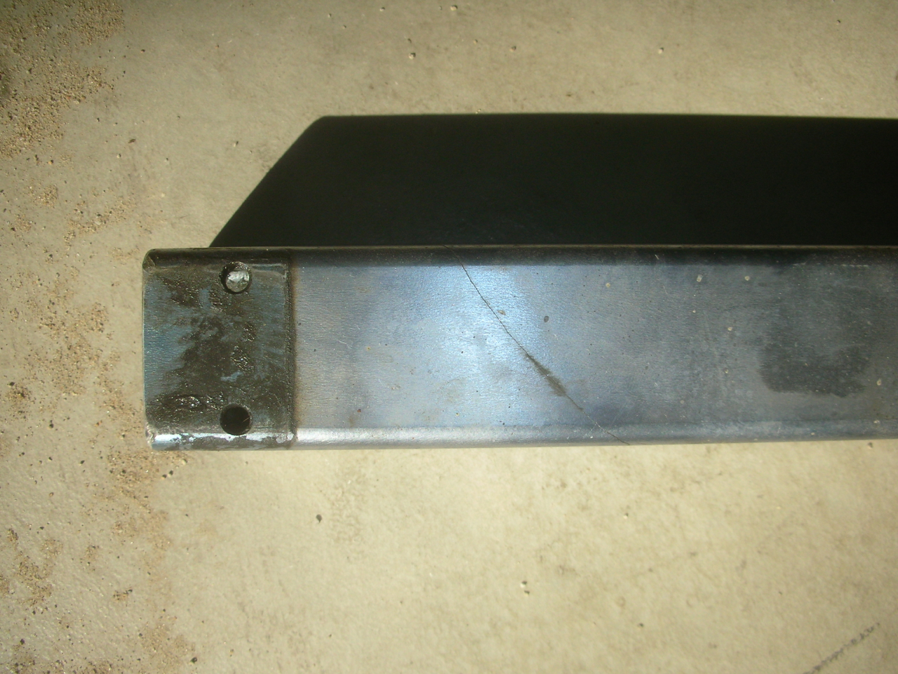
Picture Taken Of A Spiral Crack – 15 March 2008
Inspections Are Important
I took the picture above of the spiral crack for an occasion like this. I want to show others what to look for and what it looks like. The crack shown above travels across all of that side, a second side and part of a third side of the tube. If the root tube gave way at this crack while the engine and prop were spinning it could be an issue. That Root Tube was fast approaching its MTTF. The crack was discoverred in ’08 and we replaced it with the new root tube used on the plane now.
The “Bad Side” Of Tight Tolerances
Here it is 2013, though, and my “problem” when putting the prop drive assembly back into the root tube, is that the root tube and spar hardware are in excellent shape. Because the bolt holes of these items have seemingly no wear, it took me almost two hours to get the bolts to go through the root tube and the brackets. Lining up the bolt from the inside of the root tube to go through the bracket was a true test of my dexterity and patience. I should have taken some closeups. If you saw the clearances involved and could imagine the muscle strain necessary to get the parts to line up it might be more convincing than it sounds.
Then, after all that effort I realized something that “let all the air out of the balloon”. That was “it” for the day.
Both Shafts & Pulleys In Place
The Next Day (Destined To Be Another Short One)
I got up the next morning and the “depression cloud” I was under from the previous day had lifted. I decided to get right back on the job. The reason I had left in “deep chagrin” the previous day would be the first order of business. Here it is:
If you roll back a number of photos, you will see one captioned “The Drive Assembly (Sans Pulleys)“. The wide aluminum cylinder in the middle of the shot is the carrier housing for the front bearing of the propeller shaft. There are two holes through this cylinder that are to line up with two more holes on either side of the root tube. There is an AN bolt to run through these 4 holes that fixes the housing so that it and the bearing do not turn inside the root tube.
The smart way (the ONLY way) is to insert the prop shaft assembly into the root tube, spin and locate the holes, match them with the root tube holes and insert the AN bolt through the whole group FIRST. THEN attach the trailing edge spar bolts. If you did it the way I did, and attach the trailing edge spar bolts FIRST, and the forward holes did not happen to miraculously line up, you have no way to revolve the bearing carrier inside the root tube to line up the holes. Yeah, you can take it all apart but, I really, really didn’t want to go through that again.
The shock I underwent upon discovering this dilemma I had put myself in, robbed me of all strength and desire to attempt any more wrenching that day. Crushed, I stumbled home in self disgrace.
Steve To The Rescue
Fortunately for me, Brother Steve Ewing was working on his GT-400 in the other hangar at Selby Aerodrome. I described my dilemma to him. It turned out he had been through the same thing years ago and had the solution. YES! He handed me a “pick”. This marvelous device is basically what I would call an “industrial ice pick“. I shot some penetrating oil through the bolt hole to help the process and then, using the pick, was fairly quickly able to turn the carrier inside the root tube until the holes lined up. Man. This made my day! (At least until it was time to put on the Powerfin…)
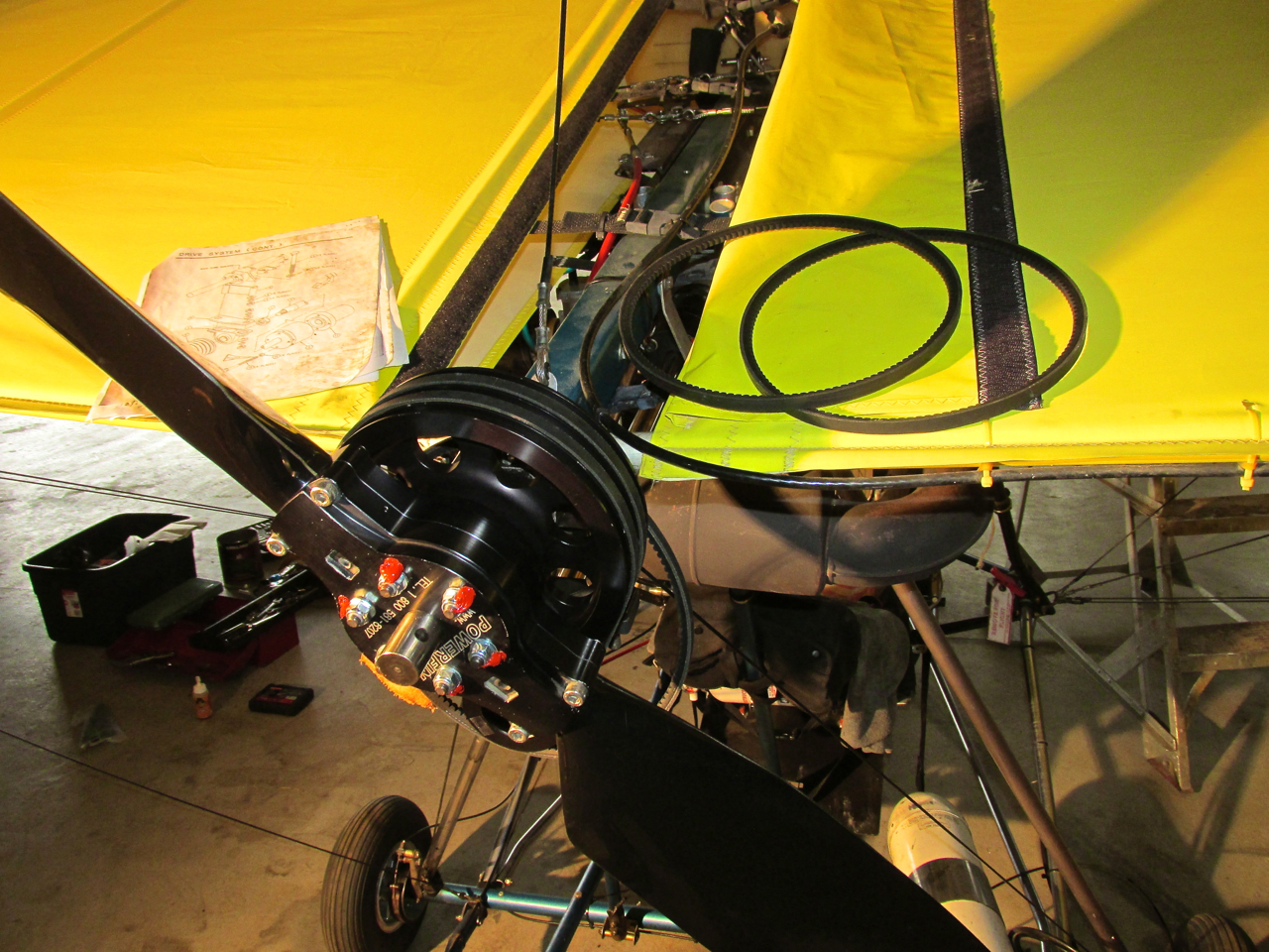
Remember! This Is A FIVE Belt System!
Home Stretch-Itis
By now I could see the end of the tunnel. I had been meticulous throughout the entire process and continued that diligence while reattaching the propeller. I torqued each prop bolt to the exact specification. Even though not required, I also put little dabs of RTV on each nut to serve as “torque seals”. Again, though, I had a sequencing issue…
The Proper Order
There are times when assembling things that you are allowed great latitude as to choosing what part to put on first and what part to put on last. Other times there is no choice. You must follow a proper sequence. The 5 Belt Pulley Speed Reduction System on my Quicksilver has a bolt/plate adjustment to tighten the belts after they are applied. There is not a lot of “overhead” and the “inside 3 belts” must be slowly and carefully “worked” from the edge to the center of both pulleys. The smart way to play this game is to put 3 of the belts on the shaft before the large pulley goes on, put the remaining 2 belts on the aft side of the pulley and then put on the propeller. If you forget to put the 2nd set of belts on before you put on the propeller – it will not work. You will bust your brain trying to make this Chinese Puzzle work. I’m standing there knowing I HAVE SEEN with my own eyes magicians do basically the same thing putting rings through rings on TV a hundred times. Even though I know they use trick devices, I’m hoping I can make it work with my will power. It wouldn’t.
Not even “Quicksilver Steve” had a miracle in his trick bag to fix this mistake. I had to bite the bullet and take the prop off, put the remaining 2 belts on and THEN the propeller and then re-torque all the bolts.
Superstition
Once I fixed the belt problem, a superstition I have about these scenarios kicked in and obliged me to break for the day. It was the same superstition that caused me to leave early the previous day when the “Prop Shaft Fiasco” occurred. This superstition is that when I make a big mistake while working on my plane, I believe I risk experiencing a “cascade of errors” unless I break for the day. The corollary to this is that they might be mistakes I overlook that could cause problems later. Regardless of the superstition, this is not a “real job” for me, so if I get frustrated, I break off and leave it for another day.
A Successful Runup!
Odds & Ends
I was able to return in the early afternoon the next day. It was still cold and fog stood in the air. I quickly ran the belts onto the drive pulleys and torqued the prop bolts again. Then I replaced all the fuel lines. After that I installed a number of “stand-offs” to the fuel lines and electrical wires. I made a meticulous, closeup scan of everything around the engine and the prop area to make sure there were no loose nuts or washers that might find their way into the prop. The Moment of Truth had arrived. I pointed the tail out of the hangar for the big test.
I am happy to say the motor roared to life with only two pulls on the starter. The Rotax was smooth and steady and quickly settled into a fine purring idle. Mission Accomplished!
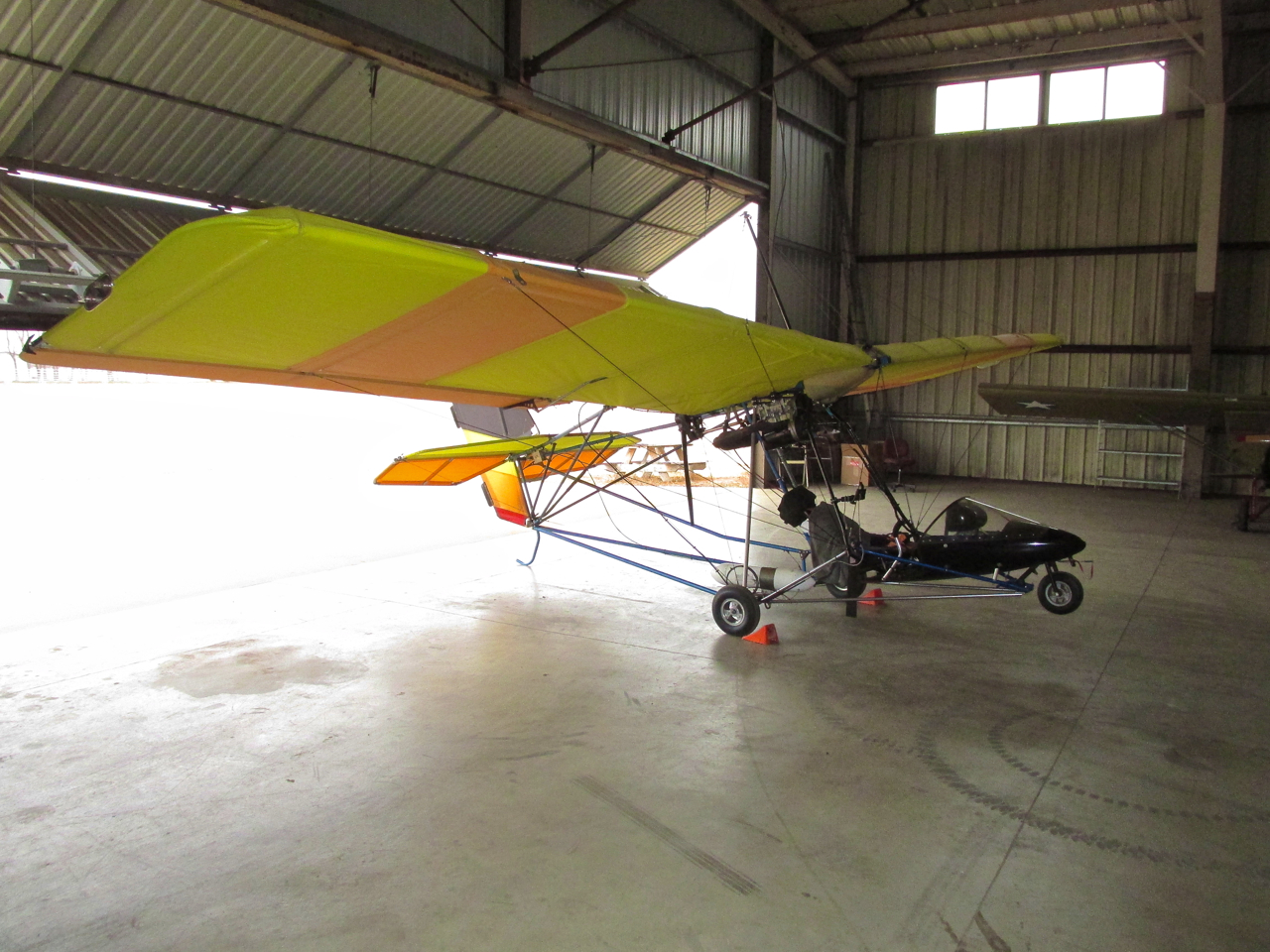
Like New And Airworthy
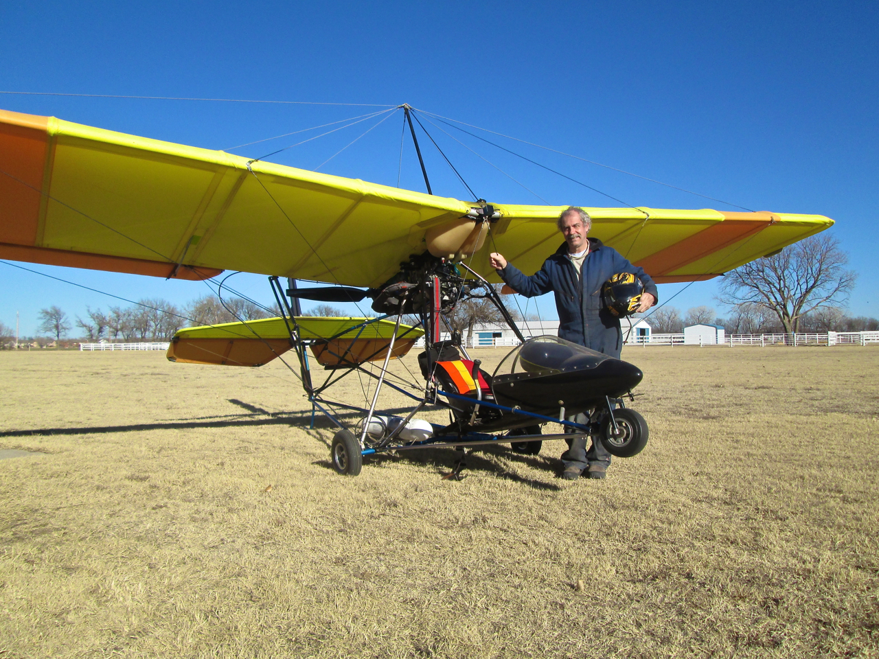
Super Saturday
Saturday was a perfect day for a test flight. The air temperature was in the 60’s. For the 19th of January in Kansas that is really warm. It was also relatively calm. I didn’t have a lot of gas so I stayed in the area and flew for only 18 minutes. Actually I had planned to only go up for 5 minutes and then land to make certain everything was secure but the MXL was performing so well I stretched my flight plan.
The CHTs were just below 300 degrees and the EGTs at 1,000. I was able to maintain altitude at a new low RPM of only 4,000. Before having the engine rebuilt, I required no less than 4,300 RPM to maintain level flight. If the engine continues to perform that well in the warmer weather this coming flying season, my range will be increased. If/when it does, you’ll be the first to know. In addition to the improved performance, I believe all this work has pushed my MXL MTBF out way past the next two to four flying seasons.
I’m glad I did the overhaul. It was worth it!
Blue Skies & Tailwinds!™
Brian FitzGerald
ps: After finishing this piece, I received in my email an article about the “math formula” that tells how long everything will live. This “new formula” they think they have discovered is nothing other than Mean Time To Failure. I appreciate their “discovery”, though, because these guys have elevated MTBF and MTTF into “Keys to the Meaning of Life“! If you want to read it the article is HERE.
Brian,
Very entertaining and interesting. Two thumbs up!
Larry
Dear Larry,
Thanks! I’m glad you liked it. I flew for about 40 minutes yesterday before the front came in. It was very nice up there.
Blue Skies & Tailwinds!™
Brian
Brian:
It appeared to be, and I’m sure it was, a lot of work! I don’t think I would have the mechanical skills or the patience for it. The work I have done on the Fisher has always turned into far more than I expected. Those small jobs, however, have greatly increased my respect and appreciation for the work my regular A&P does on my airplane and its engine. He deserves every dollar I pay him.
Glad to hear you are back in the air.
Don
Dear Don,
The plane flies excellently. I was up for about 40 minutes Saturday.
I also appreciate the work of mechanics. Sometimes I have the money to pay for work on the plane, other times I do not.
Lately I’ve had to do it…
See you soon!
Blue Skies & Tailwinds!™
Brian